
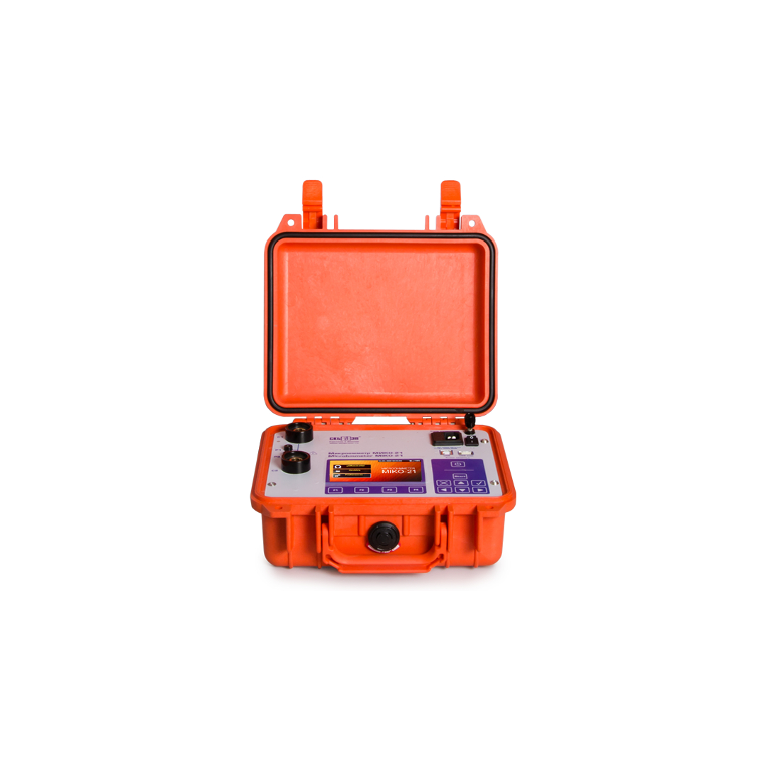
SKB EP MIKO-21
200A Micro-ohmmeter
| DAILY RATES | ||||
|---|---|---|---|---|
| Cost per Day | $143.00 | $128.70 | $107.25 | $90.09 |
| Duration (days) | 1-7 | 8-14 | 15-29 | 30 |
| TYPICAL HIRE PERIODS | ||||
|---|---|---|---|---|
| Cost | $1,001.00 | $1,801.80 | $3,110.25 | $2,702.70 |
| Duration | 7 Days | 14 Days | 29 Days | 30 Days |
Committing to 3, 6 or 12 months?
Contact us on 1300 623 605 for fantastic long term hire rates.
Contact us on 1300 623 605 for fantastic long term hire rates.
DESCRIPTION
MIKO-21 is designed for high precision measurements of DC electrical resistance in the range from 0.1 µΩ to 2 Ω with
an accuracy of ±0.05% and can test:
- contacts of high-voltage circuit breakers of all types and voltage classes;
- contactors, relays, busbars, various bolted connections, welded joints, brazed joints;
- elements of equipment for open and closed switchgears in extreme electric and magnetic field conditions;
- in research laboratories and industrial workshops.
MIKO-21 is ahead of similar devices represented on the market due to a number of functional
and technical features. For example, special measuring technologies ensure MIKO-21 compliance with the most
stringent accuracy requirements. MIKO-21 is ideally applicable for high precision resistance tests in the µΩ range.
One of the problems during contact resistance measurement with permissible error is availability of oxide films
between contact surfaces.
According to international standard IEC 60694: General Specifications for High-Voltage
Switch Gears (International Electrotechnical Commission), to control this type of error test current amperage during
testing the electric resistance in the main circuit of a HV circuit breaker shall be between 50 A and its rated value.
Test current in circuit breakers is often limited by specific values: 100 A and 200 A.
The amperage in MIKO-21 can be set in several ways:
- By selecting from a number of specified values: 10 A, 50 A, 100 A, and 200 A;
- By setting the automatic mode for selecting test current;
- By setting test current manually in the range from 1 A to 200 A at a step of 1 A.
SKB EP micro-ohmmeters are the only instruments enabling to measure contact resistance of live tank and dead tank
circuit breakers using separate automatic modes optimized for those circuit breakers.
- Mode 1 makes it possible to carry out measurements in the circuits without CT;
- Mode 2 enables to operate measurements in the circuits with CT with minimal battery power consumption;
-
Mode 3 enables to operate measurement in the circuits with CT using 100 A or 200 A test current (set by a user)
without saving battery power.
Current transformers of dead tank circuit breakers
form an extended transition process when test current is applied. Due to that measurement time is determined by the
parameters of CTs, their number, and test current. For example, for HV oil-blast circuit breakers measurement time may
be up to 30 seconds.
MIKO-21 special algorithms with automatic measurement stop prevent subjective errors and increase
number of measurements per one battery charge.
Four ways are programmed in the instrument to start resistance measurement:
-
Single is started once the cable clamps
are contacted to the tested object and followed by pressing the START button. -
Auto single circuit is initiated by
pressing the START button. The instrument will start measurement when the electric contact between the tested
circuit
and the test cable contacts is set. The test can be repeated by pressing the START button again. -
Periodic is used in
pre-specified time intervals when both hands are occupied with cable probes pressing against the test points. The
user
can choose time interval between the tests. The instrument will work continuously until the user stops the mode. -
Auto
periodic circuit is initiated by pressing the START button and used for continuous measurements. The user connects
the
current cable, and as soon as the potential contacts are connected, the measurement will start automatically. To
repeat a test, simply break contact with potential probes and reconnect.
The instrument contains a built-in database that contains nominal values of high-voltage circuit breakers indicating
the
maximum and/or minimum permissible values of contact resistance. There are also the nominal values for rejected
resistors indicating the acceptable values of the upper and lower thresholds of resistance.
The user can add / edit
/ delete the nominal values of the exact measured object.
Availability of a built-in archive of nominal values of electric resistances (main circuit resistance of HV circuit
breakers) facilitates automatic detection, and once the measured value exceeds the nominal value it is highlighted
with red colour.
This mechanism works due to either the built-in database of nominal values or the ability to add /
edit / delete the nominal data of the measured object independently.
Color graphic display of high brightness ensures easy reading on a sunny day, whereas intuitively
understandable interface with a multi-sensor display simplifies the instrument use.
The Instrument can be manipulated
either from the keyboard or from the multi-sensor display, as suits.
Communication with PC via USB or a flash card
facilitates data transfer from the Instrument to the company data base. The device can be integrated into measuring
systems under PC control of diagnostic laboratories and companies producing electric equipment.
Battery power, low weight and small dimensions ensure complete independence and high
mobility of the device in the vast territory of the substation or workshop, and the built-in memory for 2,000
measurements greatly simplifies the process of diagnostics and data transfer from the substation into the company
office.
For convenient connection to the object, there are special test cables of
different lengths and different types of clamps:
-
Test cables with Kelvin clamps for high voltage circuit breakers up
to 110 kV 2 m long (standard complete set); -
Test cables with Kelvin double hand spikes 1.5 m long for measurement in
pipelines and interrupting chambers (recommended when the device is placed near the circuit breaker); -
Test cables with
Kelvin C-clamps for circuit breakers from 10 kV to 220 kV 4.5 m and 6 m long (recommended when the device is
placed
near the circuit breaker); -
Test cables that consist of a cable with Kelvin clamp and Kelvin C-clamp for circuit
breakers from 220 kV to 750 kV 3m / 6m or 9m long (recommended when the device is places in a cradle of a lift); -
Test
cable for precise measurements and measurements on sections of the electric circuit, to the end points of which
the
test current is applied.
SPECIFICATIONS
| Specifications | Value |
| Resistance range, Ohm | 0.1 µΩ – 2 Ω |
| Current range, A | 1 – 200 |
| Number of digits in the output of the measurement result | 5 |
| Accuracy | ±0.05 % |
| Time of measurement in Mode 1, sec | not more than 2 |
| Time of measurement in Mode 2 on a dead tank circuit breaker with a built-in CT (energy saving), sec | 10 – 30 |
| Time of measurement in Mode 3 on a dead tank circuit breaker with a built-in CT (without energy saving), sec | 5 – 15 |
| Mains voltage | 90-264 V AC, 47-63 Hz 127-370 V DC |
| Consumed power does not exceed, W | 60 |
| Battery type | Li-Ion |
| Battery lifetime (in continuous operation), hrs | more than 8 |
| Battery recharge time, hrs | less than 2 |
| Built-in memory | 2,000 measurements |
| Number of tests (max. current, I=200A) | more than 500 |
| PC communication | USB / USB Flash |
| Display | Color graphic display, touch-screen, 480 x 272 pix |
| Interface, User manual language | English |
| Environmental protection with closed cover | IP 67 |
| Environmental protection with open cover | IP 40 |
| Storage temperature, ºС | -20 – +60 |
| Operating temperature, ºС | -20 – +50 |
| Relative humidity, % (non condensing) | 95 |
| Dimensions, mm | 270 х 246 х 124 |
| Test block weight, kg (lbs) | 3.3 (7.28) |
| Calibration period, years | 3 |
| Warranty period, years | 3 |
| Testing period, years | 3 |